Currently Empty: $0.00
Digging Depth and Working Reach of Spider Excavators on Hillsides
Hillside excavation leaves little room for guesswork. A retaining wall footing must reach a set depth. A drainage trench must hold a steady grade across a slope. A foundation pad must be cut into the hillside to an exact elevation. On level ground, an operator can often move the machine a few feet and try again. On a slope, every new setup means raising and resetting support legs, checking the ground again, and adding risk.
That is why digging depth and working reach matter so much on spider excavator projects. These two figures help planners and operators decide whether the machine can complete the work from a planned position. They show whether the bucket can reach the required depth, how far the machine can dig from its support points, and how many setups the job will need. Used well, they cut repositioning, keep cycles efficient, and help the machine stay within safe limits.
These measurements come with an important limit. The figures on a specification sheet describe the machine under defined conditions. A hillside rarely matches those conditions. Slope angle, support placement, ground strength, bucket geometry, and the machine's permitted operating range all shape how much of that published capability you can actually use. A machine that can reach a certain depth on flat, firm ground may not reach the same depth safely from a sloped setup.
Understanding Digging Depth
Digging depth describes how far the machine can excavate below its reference ground level under specified conditions. Manufacturers usually list a maximum digging depth, measured from the ground line where the machine stands to the lowest point the bucket teeth can reach with the boom and arm in a defined position.
Depth also differs from usable depth with control. The maximum figure often reflects the bucket at the full extent of its travel. At that point, the operator has little room to shape the trench floor, curl the bucket to hold material, or lift a full load clear of the cut. For practical work, plan to dig the required depth with some margin inside the machine's limit rather than at its edge.
Plan depth against the project's reference points. Know the required depth relative to the finished grade, a benchmark, or grade stakes, and confirm how that relates to the ground where the machine will stand. A footing that sits 4 feet below finished grade may need a much deeper cut from a machine set up higher on the slope.
Key takeaway: Digging depth is measured from the machine's own ground level under defined conditions, so confirm how slope position, support setup, and bucket angle change the usable depth, and plan to work with margin inside the published maximum.
Working Reach and Horizontal Distance
Working reach describes how far the attachment can extend from the machine's reference point. Manufacturers often list maximum reach at ground level, measured horizontally from the center of rotation to the farthest point the bucket can reach. Related figures may include reach at various heights and depths.
Reach determines how much ground the machine can cover from one setup. On a hillside, that matters a great deal. Every repositioning means raising the legs, moving across uneven terrain, choosing new support points, and leveling again. A machine with useful reach can often complete a longer trench section, a wider pad, or a deeper cut from a single stable position.
These effects grow stronger when the boom extends downhill. On a slope, the downhill support points already carry a larger share of the machine's weight. Extending the boom and lifting a load on that side adds more. A reach that is acceptable when working uphill or across the slope may exceed safe limits when swung toward the downhill side.
Use the manufacturer's reach chart for the exact machine configuration. Reach diagrams show the full arc of bucket travel at different heights and depths. Load charts, where provided, show how lifting capacity changes with reach and height. Read both together. A point the bucket can physically reach is not always a point where the machine can lift a full load safely.
Plan work positions so most digging happens within the comfortable middle of the machine's range. Reserve full reach for occasional movements, light loads, and situations the manufacturer's charts confirm are within limits.
Key takeaway: Working reach shows how far the bucket can extend from the machine, but extended reach reduces capacity and shifts loads onto support points, so use the model-specific reach and load charts and avoid full extension toward the downhill side.
Slope Position and Support Setup
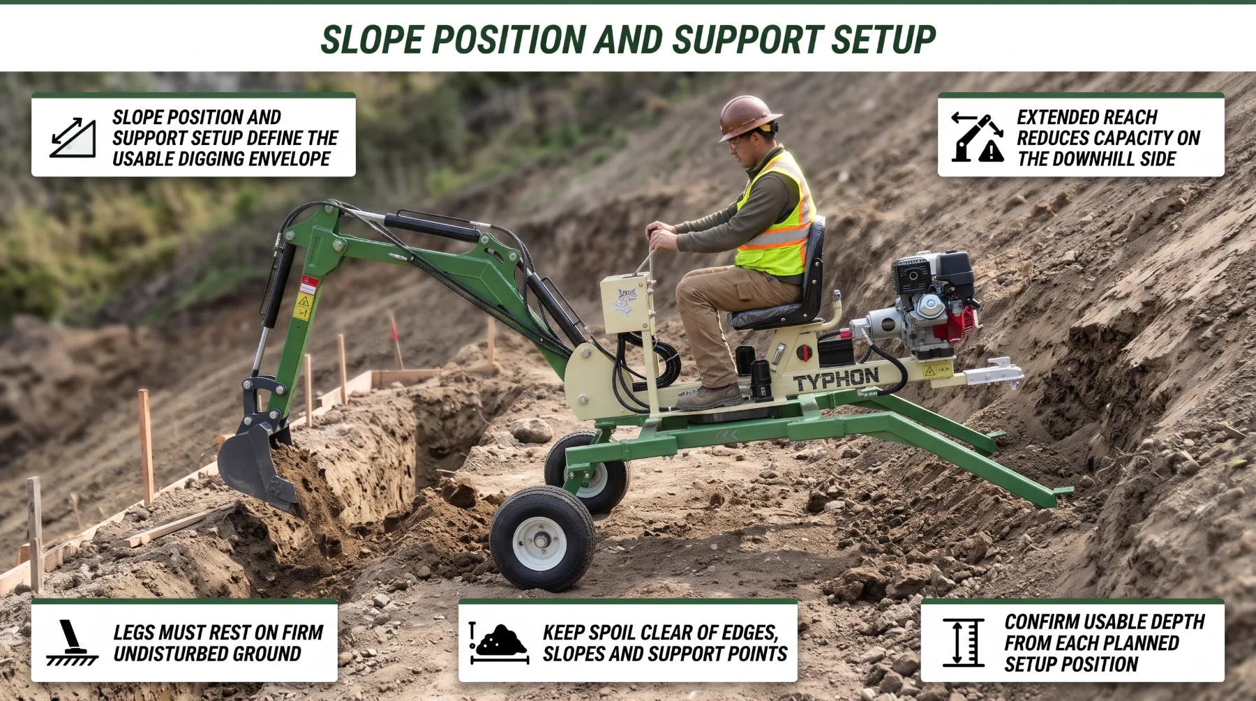
Digging depth and working reach only mean something once the machine has a stable position. On a hillside, support setup determines both the safety of the operation and how much of the machine's digging envelope is available.
The excavator must be positioned within its permitted slope and support limits. Spider excavators can adjust their legs to suit uneven terrain and level the upper structure on a slope, but every model has limits on leg extension, leveling angle, and the slope on which it may operate. Confirm these limits in the operator's manual before setting up.
Support legs should rest on ground capable of carrying the machine's loads. Each leg carries a changing share of the machine's weight as the boom swings, extends, and digs. When choosing support points:
Use firm, undisturbed ground or solid rock: Avoid loose fill, recently disturbed soil, and eroded areas.
Stay away from unsupported edges: Keep legs back from drop-offs, retaining walls, excavation faces, and steep banks that could break away.
Check for loose rocks: A leg placed on a loose rock can shift suddenly under load.
Watch for water: Saturated soil, springs, and seepage weaken bearing capacity and can change during the job.
Use approved support pads where specified: Pads spread load over a larger area when the manufacturer approves them, but they do not make unstable ground safe on their own.
Support setup has a direct effect on the digging envelope. Leg height and leveling change the height of the boom pivot above the ground. Raising the machine on its legs can reduce the depth the bucket reaches below the surface, while a lower setup may increase depth but limit swing clearance over obstacles. Plan the setup with the required depth and reach in mind, then confirm the result against the reach chart.
Do not extend the boom to compensate for unstable positioning or inadequate support. When the ideal setup point is unsuitable, crews are often tempted to set up on safer ground farther away and stretch the boom to reach the work. That shortcut combines reduced capacity at reach with uneven support loads and can push the machine past its limits.
Key takeaway: Position the excavator within its permitted slope and support limits, place legs on ground that can carry the machine's loads, and never extend the boom to make up for an unstable or poorly chosen setup.
Bucket and Attachment Effects
The attachment at the end of the arm changes both the digging envelope and the loads the machine carries. On a hillside, where stability margins are already reduced, attachment choice deserves careful attention.
Bucket size and shape affect digging geometry. A longer bucket places the teeth farther from the arm pivot, which can change both the depth and reach the machine achieves, as well as the bucket angle at the bottom of the cut. A wider bucket increases the volume removed on each pass but also increases digging resistance. Different bucket profiles affect how well the machine can cut a clean trench floor, shape a slope, or work close to a vertical face.
Bucket size also affects load. A larger bucket holds more material, and dense or wet soil can quickly bring a full bucket close to or beyond the machine's capacity at reach. The attachment's own weight adds to every lift. As reach and depth increase, both effects become more significant.
Every attachment must match the machine's mounting system, hydraulic requirements, and rated capacity. Confirm compatibility in the manufacturer's documentation. Before work, check that the coupler or pins are clean, undamaged, and fully locked, and test the attachment through its full range of motion in a safe position.
Key takeaway: Bucket size and shape change both digging geometry and load, so choose an approved attachment suited to the material and the required depth and reach, and avoid oversized buckets for deep or extended work.
Excavation Sequence
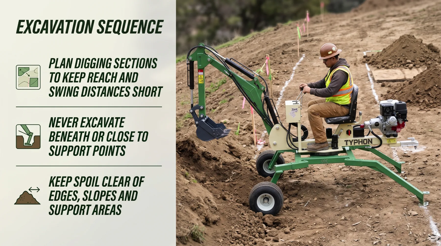
A planned excavation sequence makes the most of the machine's digging depth and reach while protecting stability. Without one, the machine often ends up working at full extension, swinging long distances, or digging toward its own support points.
Plan the direction of work so the machine moves onto solid, undisturbed ground rather than toward freshly cut edges. On many hillside jobs, working from the top of a cut and stepping down in stages, or working across the slope from a stable bench, keeps the machine on firmer footing than digging toward it from below.
Avoid excavating beneath the machine's support points. Digging under or immediately beside a leg removes the ground carrying it and can cause sudden settling or tipping. As excavation advances, confirm that every leg remains well back from the cut face. Watch for cracks forming between the excavation and the support points, which signal that the ground is moving.
Keep the area below the work clear. Rock and soil disturbed during excavation can travel downslope. Establish an exclusion zone below the machine and the excavation, and brief everyone on site before work begins.
Key takeaway: Plan digging sections, spoil placement, and repositioning together, work in short controlled sections that limit boom extension, never excavate beneath support points, and keep spoil away from edges and slopes.
Confirming the Working Envelope
The working envelope is the full range of positions the bucket can safely reach from a given setup, accounting for depth, reach, height, swing, and load. Confirming it before excavation begins is the step that turns specification figures into a safe, workable plan.
Check clearance from overhead hazards, utilities, and nearby structures. On a hillside, the boom may rise higher relative to the ground below the machine than on level terrain, and power lines, tree limbs, and structures can fall within reach during digging or swinging. Complete the required utility locating process before excavation, such as contacting 811 in the United States, and arrange private locating where privately owned lines may be present. Expose marked lines using approved methods before mechanized digging continues near them.
Mark the envelope on site where practical. Grade stakes, paint lines, and flags showing the excavation limits, spoil areas, and exclusion zones give the operator and crew clear references. A spotter positioned safely outside the swing radius and visible to the operator can help monitor clearances the operator cannot see directly.
When any of these appear, reposition, prepare a better setup, change the method, or select different equipment. Pushing a machine beyond its envelope to finish a section rarely saves time and puts the operator and crew at serious risk.
Recheck the envelope as work progresses. Excavation changes the ground, water can soften support points, and each new setup creates a new envelope that must be confirmed.
Key takeaway: Confirm the working envelope using the exact model's manual, reach diagrams, and load charts, check clearance from overhead hazards, utilities, and structures, and stop whenever the required digging position falls outside the machine's safe operating range.
Conclusion
Digging depth and reach are useful planning measurements, but hillside work also depends on stable support, attachment choice, and machine configuration. Published depth is measured from the machine's own ground level under defined conditions, so slope position, support height, and bucket angle all change how much of that depth is usable. Working reach shows how much ground the machine can cover from one setup, but extended reach lowers capacity and shifts load onto support points, especially toward the downhill side. Stable support within the machine's permitted limits is the foundation for every cut, and the boom should never stretch to make up for a poor setup. A planned excavation sequence keeps work in controlled sections, protects support points, and places spoil away from edges and slopes. Approved attachments sized for the material and the required depth keep loads and geometry within limits. Confirming the working envelope with the exact model's reach and load charts brings these factors together before the first bucket enters the ground. When you plan each setup with care and work within the machine's limits, you avoid unsafe boom extension and repeated repositioning while completing hillside excavation accurately and productively.
FAQs
Does maximum digging depth remain the same on a slope?
Not always. Machine position, support setup, and ground conditions may reduce the usable digging envelope. Published depth is measured from the machine's ground level on firm, level ground with a defined configuration. On a hillside, digging uphill, raising the machine on its legs, or working with a different bucket angle can all change how deep the bucket reaches relative to the target surface. Confirm usable depth from the planned setup using the model's reach diagram.
Can longer reach improve hillside productivity?
It can reduce repositioning, but extended reach must remain within the machine's load and stability limits. As the boom extends, lifting capacity drops and more weight shifts onto the support points on that side, particularly when working downhill. Plan setups so most digging happens within the comfortable middle of the machine's range, and use the manufacturer's load charts to confirm capacity at the reach required.
Where should spoil be placed?
Use a stable, planned location away from support points, excavation edges, and routes where material could slide. Avoid loose downslope piles that could roll toward workers or structures, keep spoil clear of drainage paths, and arrange removal as work progresses on tight or steep sites. Keep the area below the work clear of people and equipment.
How should operators confirm reach?
Consult the exact model's operating manual and reach diagram for the intended configuration. Confirm that the diagram matches the installed boom, arm, and bucket, compare the required depth and reach with the machine's range from each planned setup, and check load charts for capacity at those positions. Verify clearance from overhead hazards, utilities, and structures, and stop if the required position falls outside the machine's safe operating envelope.